
Atmel AVR WiFi Radio WhereAVR Videoverlay EthIRnet IC-3200A Ballooning Lost At Sea Buzz-O-Matic Other Stuff APRS Tracker Generator Natural Gas Conversion Allstar Node 43710 Allstar USB FOB Local Radar 
|
The Wifi Radio Project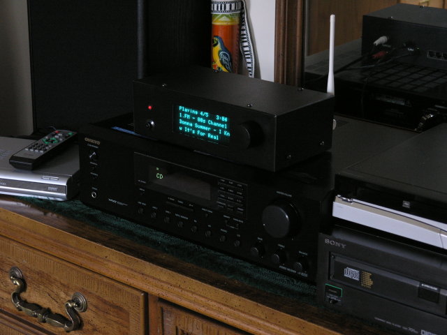
IntroductionI'm one who often has the radio playing when I'm working on a project or unwinding at the end of the day. And while there are a few good radio stations still around, there are times I'd like to listen to a genre that a local station just doesn't cover. Ever since stations started simulcasting on the internet, I've been a big fan. You name it, and someone probably has a station dedicated to it. This page outlines my project to home-brew a dedicated box for 'tuning in' these online stations. Sure, I could have bought one for $100 or just used my computer (which I've often done, and still do), but I wanted to make something to match the other stereo hardware I have. I also like that I can personalize every aspect of the design, and put to use some of the hardware I've collected over the years. Background InformationInspiration for this project came in no small part from Jeff Keyzer over at mightyOhm.com. If you haven't seen his site yet, do be sure to visit it and see what he's done. I'll reference it later when I speak of modifying the firmware in the wireless router. I also collect (horde?) a lot of hardware. One obsession seems to be displays, especially vacuum fluorescent. This project had to have one. It made matching my stereo and cd player easier since they employ them too. I also collect knobs, buttons, dials, switches, etc. And so I was able to match the look and feel of the equipment on my dresser. Hardware ComponentsFirst things first, I had to collect all the parts I wanted to fit into the radio. There would be the Asus WL-520gu router, the USB audio adapter, the vacuum fluorescent display (VFD) I recently found on ebay, various knobs/buttons, and some sort of processor board to pull everything together. For small projects like this, my trusty ATmega8 has never let me down, so I felt it was up to the task. Shown below is a board I'd designed for an LCD serial backpack, but repurposed for this project. I don't have a formal schematic for it handy, but it's pretty simple and I'll explain gritty details of the electrical design further below. 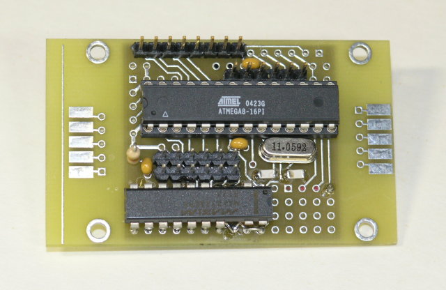
The board itself hosts the microprocessor, a Maxim MAX233 serial level converter, a few capacitors, a pull-up resistor for the reset line, and the headers for connecting cables. I will mention now that I probably didn't need the level converter, as it's only there to talk to the VFD. If you look closely, I clipped some of the leads and a voltage divider for talking to the router is hidden underneath. The display is made by IEE and is the 036X3-100-05420 model. I discovered it accepts RS-232C voltages as well as the +/-12v levels, but in the process of chasing down a problem which turned out to be a timing issue, I added the MAX233 purely to limit potential problems with the Atmel perhaps not being able to drive the serial line of the display properly. USB Audio AdapterAs Jeff mentioned on his site, a number of USB audio adapters work. And, well, a number don't. I have used the board out of a computer headset Radio Shack used to sell. Sorry I can't be much more specific about it, as it's no longer sold. For more on what is and isn't supported, be sure to check out the MightyOhm WiFi Radio Forum. A Case, Knob, and ButtonIt's at this point, I really wish I'd taken a picture of the original device which lived in the case it so valiantly donated. It was an old-school composite video fader made for easing scene changes in home-edited videos. I think I found it in a junk box at a hamfest for 50 cents. Anyhow, it was collecting dust and [just barely] fit the components, so it was destined for a new life. After cutting, drilling, sanding, priming and painting, (and some mounting) this was the result: 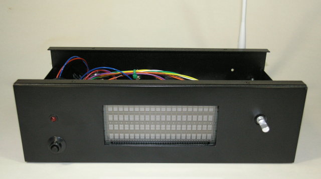
I made the opening for the display using a Dremel and its cutoff wheel. 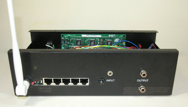
And I opened the back for the Ethernet jacks on the router using a sheet metal nibbler. The audio output sockets were the composite video in/out ports in their previous life. The 1/8 inch jack over the "input" label is the infrared signal input line from the Onkyo receiver (more on that later). The Display FilterYou can see in the above photo that it's pretty obvious where the character cells are in the VFD. I never gave much thought to the acrylic placed in front of fluorescent displays until I ran across Mark Hennessy's preamp project. I used to work in technical theater, and had a few books of sample gels, which are the plastic filters placed in front of stage lights to create different colors. I spent half an hour holding pages of that book in front of the display. And boy, the filter used makes a huge difference! I never knew you could really make a VFD red, but I believe it now. That said, the pages weren't big enough for me to rip out and use, so I had to find a cheap filter for myself. Instead of going to a theatrical supply store, I found some vinyl baskets at the Dollar tree in blue and green. I couldn't decide which color to go with, but as it turns out I needed both. After cutting two rectangles out of the baskets, I sandwiched them in between the case body and the case cover. The green is on the outside: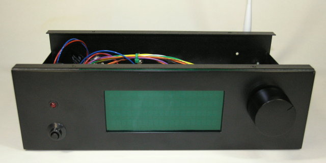
Makes a big different, doesn't it? Makes an even bigger difference to the contrast of the display: 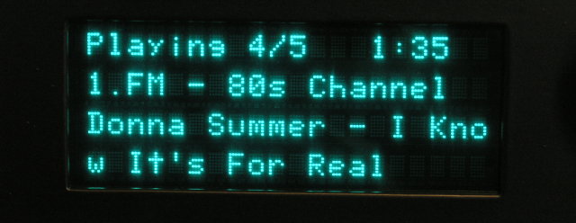
Mounting The BoardsLet's continue the picture-laden story with even more! First up is a shot showing the router on bottom and display on the left:
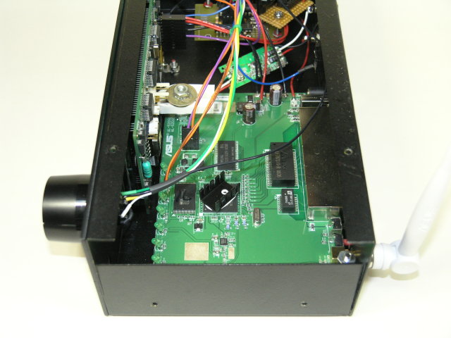
Only one bracket bolts directly to the display and anchors it to the bottom of the box. This keeps it from sliding around. I hold it against the front of the box with a piece of foam and pressure from the white block bolted in the middle. The bolt comes up from the bottom of the box and is also supporting one side the router board. On the left, you can see the back of the rotary encoder. On the right, the power button and "wireless activity" LED which used to be mounted on the router:
Using long bolts makes stacking boards easy. It just makes removing boards quite the process when they are on the bottom of the stack! 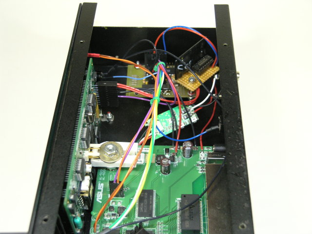
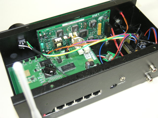
Here is the USB audio board out of the headset, the one solid mount for the display, and the threaded bolt with boards stacked. I ran wires directly to the USB connector on the bottom of the router. 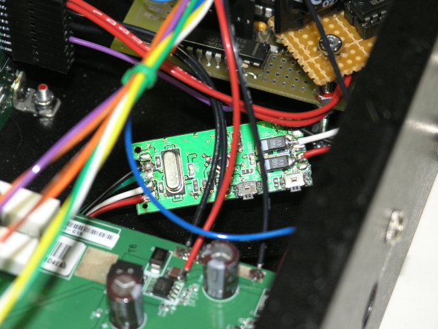
And finally, the connectors leaving the ATmega board running all over: 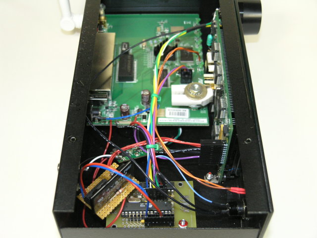
The perforated board in the bottom left holds a solid-state relay module. I added it to power down the display when the power is "off" since the hot cathodes draw a lot of power even when nothing is shown on the display. Yes, the relay is overkill, but I scrounged it from a trash bin. The integrated circuit on the board is just a ULN2003 Darlington array to buffer the output of the microprocessor to drive the input of the relay. It's overkill as well, as the microprocessor could probably sink the necessary current to drive the internal LED. Router SoftwareFor the most part, I followed along with Jeff on his blog as he replaced the firmware in his router to OpenWRT, installed additional software, and talked to mpc through the serial port. I recommend that you also set up your router just like Jeff did, at least at first. I made a few changes to my install by the time I was done, and they are primarily in the interface.sh file. I run a higher serial speed, load an initial playlist file using 'mpc load', and added one more status line to get playlist choice and elapsed playing time. Also, My Atmel code directly generates shell commands, so I did -not- modify /etc/inittab like Jeff did in part 8 on his site. This also allows me one more "back door" to log in with in case I screw something up. Sure, the Atmel gets a bunch of 9600 baud garbage during router boot-up, but it doesn't hurt anything.Regarding the commands that the Atmel sends to the router, I stuck with shell commands that a user would type. I start and stop playback with 'mpc play' and 'mpc stop', respectively. It's pretty dull stuff, really. The last note I need to mention is that the Atmel expects six playlists, labeled "1" through "6", for mpc to load into mpd. If they aren't there, it doesn't hurt anything; mpd simply stops playing. In my box, "1" is the playlist Matt had in his 'interface.sh' file, '2' is a list 80's music stations, etc. You get the idea. Atmel ATmega8 SoftwareYou will find the source code for the ATmega8 controller in a link below. It is written in C, so if you are familiar with the Arduino, you should also be able to follow along. I tend to comment every line I can, so you can enjoy or ignore as you choose. But to a great extent, it fills in for the lack of a formal schematic. For example, the serial transmit pin of the Atmel is connected to the input of the router through a 1.8k/3.6k voltage divider (to drop from 5v to 3.3v). I mention it in the Control.c file. It really isn't any more complicated than that. Hope you don't think that's too lazy, but everyone's design will be different and you'll probably make stuff up off the cuff if/when you build your radio too!Everyone has their own coding style, and I'm no different. You'll find I mainly stick with code on the left and pseudo-code comments on the right. It just clicks with me. Also, you'll see I seldom if ever use delays. Instead I use state machines with a home-brew scheduler for all my functions. One reason I never got into the Arduino is I looove my hardware timers. :) Data from the router is parsed in Messaging.c, and you'll see I rolled my own version of strcmp, strcpy, etc. I pull the song title, stream name, volume level, etc. out from there, and then pass it on. Called functions begin with the abbreviated name of the source file you can find them in. For instance, CtrlIdle() is found in Control.c. Using the SoftwareI put this with the software since this explains how the interface functions. And well, the software follows these behaviors. Pushing the rotary encoder cycles through the song (default), playlist, volume, and dimmer displays. In each screen, you can turn the knob to change song, playlist, volume, or brightness, respectively. The screen times out after 5 seconds and returns to the default screen. Songs automatically start playing when a song or playlist is modified. The button on the left under the wireless activity LED is the power button. It tells the router to play or stop playing songs, and controls power to the display. Right now, the router and Atmel are powered all the time. I can verify that the router is streaming or not by watching the flicker of the LED. If it's flickering, I should be hearing audio! Remote InterfaceThe radio can of course be controlled by logging into it over Ethernet (as shown in Jeff's blog). But what about controlling it from an IR transmitter? Well, that's easy to add, especially if you have a newer stereo receiver which shares its IR signal with other components through a jack on the back. I recently purchased an Onkyo TX-8255, specifically for listening to the radio, be it AM, FM, or internet, and it happens to have a connector on the back for controlling other equipment. I sat down with an oscilloscope and was able to figure out the protocol and how it represents buttons on the remote. The line is typically low, but each button press generates a 3 millisecond(ms) high (at 4 volts), a 0.5ms low, and thirteen more 0.5ms highs, separated by 0.5ms OR 1.0ms lows. Whether the lows are 0.5ms or 1.0ms in length are how the thirteen bits are represented, and each button generates a different pattern. I may not decode them exactly as Onkyo intended, but it works great just the same. FeedbackI welcome questions and comments. E-mail me at (that's 'me@') my website name. Hope you enjoyed this project! Downloads!Source: wifiradio20100116.zip Router shell script: interface.sh |
|---|
